Thursday, September 30, 2010

WS3-7

Idle air control :
This is a solenoide which is controlled by the ECU . This solenoide controls the amount of air bypassing the throttle butterfly and entering the intake manifold to keep the car running when the engine is at idle and the throttle fly is not open to allow air inside the intake manifold so it can have sufficient air to keep the car running smoothly. It is a PMW and the frequency increases as the engine RPM increases and the On time gets smaller.
WS3-6

WS3-5


WS3-4
 O2 sensor:
The O2 sensor works in comparing the amount of oxygen in the exhaust and amount oxygen in the ambient air ... above we can see the oxygen sensor is operational which normaly has to reach 300 deg/C and after that ECU goes in to closed loop which means the ECU uses oxygen sensor to see if the air/fuel mixture is lean or rich and if rich it will make it leaner and when lean it will make it rich and we can see this cycle in the above photo.
WS3-3


Ignition Primary pattern :
This pattern is a good way to check the condition of the ignition circuits . It also uses string theory so as the firing voltage increase the burn time decreases and vice-versa.
Firing voltage: The voltage or push needed for the spark to jump the spark plug gap .
Burn voltage: Voltage needed to maintain an arc or spark between the spark plug electrodes so it can burn all of the fuel in the combustion chamber.
Burn time: The length of time in which the arc or the spark maintained , its a good indication of the state of the secondary circuit components (spark plugs , HT leads , King lead , distributor cap , rotor and secondary ignition coil )
Dwell time: The length of time in which the primary circuit is grounded (turned on) for prior to the each spark . It is to build enough magnetic field in the primary so then after collapsing it can induce a high enough voltage in the secondary windings .
WS3-2

 The frequency and the ampiltude of the voltage changes as the magnetic teeth speed increases or decreases . As the teeth magnetic field approaches the sensor it creates negative voltage first then as it gets next to the magnet there is no vltage created because no magnetic field are being crossed , as the magnetic teeth field starts going away from the magnetic pick up sensor it craetes positive voltage which we see on the graph above or the video below will show as we rev the engine up the frequency and amplitude increases rapidly.
 WS3-1
 Petrol Injectors:
At the voltage supply the injectors are closed because they havent been earthed out by the ECU yet at the point where we have injector opening the ECU earths out the injector and the solenoide inside is energised to open the injector and the Back EMF is produced as the magnetic field collapses on itself which creates a hight peak ... to keep the injector open only a little bit of energy is needed compare to when they need to be opened . after the injector is closed the voltage goes back to supply voltage till the next time its earthed out by the ECU to be opened and this opening and closing is also known as PWM. which is sent from ECU .
WS2

-Toyota 4Age
By looking at the vehicle workshop manual we can obtain the correct pin to bridge and with the key on we can put the car into diagnostic mode , I really like this as we dont need expensive scan tool only a jumper wire , also so easy to use as in which direction you should be looking at , It does not always tell you what we exactly need to check or where to look but its always a good start .
- After looking at the workshop manual ... it states the ignition should be in the ON position and bridge terminal TE1 and E1. and this puts the car into diagnostic mode and we can use the car's own ECU it can tell us what faults it has logged on its memory .
- After fault codes were put in by the tutor we put the car in to diagnostic mode and the codes we found were : 2 & 7 these faults made the car run very rugh and keep turning off at idle .
There were also 3 & 5 which we got because we had the ignition module unplugged ( code 3) and unpulging engine RPM sensor inside the distributor ( code 5)
- By looking at the list below we can see what does each code number means

- After doing the visual inspection at faults found : I found the TPS sensor plug was not in properly and also the vacuum sensor plug was not in properly so the ECU was not getting good signal from these sensors .
- I repair these faults by making sure they were plugged in properly .
- To check and make sure I turned the car on and now it was running with out a problem and was running smoothly at idle and also when reved up .
- To clear the fault codes I disconnected the battery and left it for a couple of mins and then connected the battery back to the vehicle . I put the jumper wire back in TE1 and E1 and turned the ignition on .
code 1 means everything is normal and there are no faults detected by the ECU
- Code 2: Interupted signal from the manifold vacuum sensor . This fault will cause the vehicle to not run smoothly as the ECU doesnt know what the vauume pressure inside the intake manifold is ... also how much engine load we have specially when driving , not so much at idle and how much load its carrying and might struggle going up hill since it has no value from the vacuum sensor . It will cause the engine run poorly and to make the engine emission to rise because its not running at the optimum condition .
- Code 7: Interupted signal from the TPS . This fault will cause the engine run very poorly as the ECU has no idea what the driver intend is and how much air is coming inside the intake manifold and whether the diver is accelerating fully or half way and what he wants to do exactly . This will cause the engine to run poorly at idle or even more when driving and cause the emissions to rise as the ECU can not find the optimum condition for the vehicle.
- We can also check the supply wire voltage , check the ground by Voltage droping the earth wire with a good ground e.g negative post of the battery . also we can check the signal wire and make sure it is changing in the right manner and check all these information with manufator spec to see if it is within specified spec.
WS1
Checking the voltage at the injectors and the battery
Make : Toyota Model : 4AFE (Grouped injection)
- After turning the engine on we can listen to the injectors opening and closing which sounds more like ticking than any thing else . I put the end of the screw driver on the body of the injectors and the plastic handle of screw driver on my ear and could hear ticking from the injectors . This shows each injector is opening and closing and as long as there is fuel available to the injectors , it also means that they are injecting fuel into the cylinders and they are opening and closing . All injectors OK and could hear ticking from all 4 .
- Bychecking the voltage at the injectors we can also make sure they are getting the right voltage which is the battery volatge ( 13.50 Volts) and this will show if there is high resistance in the circuit and no poor connections. These results are within the manufactorer spec which is good under 0.1 volts from the battery supply .
 - Another way of checking to see if injectors are working properly is to back probe each injector and hook up a LED tester to it ... as the ECU grounds each injector so those the LED tester and it consequently turns the LED on ... this happens so quickly that makes it look like the LED is always on especially when we rev the engine up . This can show if the injector is repetetive is in order and is getting a good PWM.
 - By using the multimeter set to duty cycle we back probe the injectors and connect our multimeter to the injectors . we can see how much of the time they are staying open at idle . shows that the injectors are staying opened roughly around 2.2-2.4% of the time to spray petrol in the engine . which shows that the engine is running lean at idle.

- Having the multimeter on the same setting and back probed to the injectors we rev the engine up to see if the duty cycle changes and by how much . This results show that when we rev the engine up our injectors are staying open longer to spray more petrol as we need more to be able to increase the RPM , ECU does this to comply with the driver intend which picks up from TPS , MAF ... My results show when we accelerate the engine with a short fast throttle , the injectors are staying open 34-37 % of the time which shows more of a richer mixture than idle .

we can see the frequency of how many times per second our injectors are opening and closing . we first do this at idle . Our results show that the injectors are opening and closing 47.5-48.2 Hz times they are opening and closing per second . This shows a lean mixture.

- We now repeat the steps above but reving the engine for a short time to see if the frequency of the injectors are changing or not and by how much . Our results show that the frequency has more than doubled and that also tells us the injectors are opening and closing 112.7-116.1 Hz times per second . this tells us that we have richer mixture since the frequency of the injectors opening and closing has more than doubled .
 - Now using this formula " Pulse width ms = (% duty cycle x 100)/frequency"
would show us how long in ms the injectors are staying opened .
since we have grouped injection I am doing cylinder 1&3 and 2&4 together .
At idle :
Cylinder 1 & 3 :
Pulse width ms = (2.2 x 100) / 47.5
= 4.63 ms
Cylinder 2 & 4 :
Pulse width ms = (2.4 x 100) /48.2
= 4.98 ms
Reving up :
Cylinder 1 & 3 :
Pulse width ms = (37 x 100) / 112.7
= 32.83 ms
Cylinder 2 & 4 :
Pulse width ms = (28 x 100) / 116.1
= 24.11 ms
Conclusion :
This is a very good way to check how good they are working . Easy and faster way to check injectors with out pulling them all out and if we dont have pattern tester or flow rate tester then there is actually no other way to test weather they are working and how long they are being opened for in realtion with RPM .
Tuesday, September 28, 2010
Wiring up an ignition system
 Above also similar to 3rd diagram is a coil over ignition system which each spark plug would be using their own coil , and sometimes even their own ignition module (darlington pair ) built in one and located on top of each spark plug .
 Above is a wasted spark ignition system consisting of function generator to trigger the module , and darlington pair (ignition module) wasted spark coil and 2 spark plugs.
 Above is an ignition module (darlington pair) functin generator to trigger the module , coil and a spark plug .
 Above we have an ignition module (darlington pair) disributor to trigger the module , coil and a spark plug .
Testing ballast resitors


Checking ballast resistors is very easy ... unfortunatly the ones we used didnt have any idetification still written on them so we couldnt get any specs .
Ballast No1 measured resistance was 1.4 Ohms.
Ballast No2 measured resistance was 1.5 Ohms .
most of the ballast resistors have a similar resistance so if significantly higher than 1.5 Ohms or signifiacntly less can tell us there is an issue with this resistor but ofcourse if we had the spec it would have been much easier to do this ...
Also none of these ballast resistors are serviceable.
Wasted spark coil pack
checking the resistance of secondary windings because it was not possible to check the primary
Coil #1 secondary was 6.91 Kilo Ohms
Coil #2 secondary was 6.82 Kilo Ohms
Pin outs :
1= + positive supply 12 V
2= - negative earth
3= Signal 1
4= Signal 2
Testing ignition coils off-car
 Above shows how to check the internal resistance of the primary windings.

Using a multimeter I recorded the default error of the multimeter which was 0.1 Ohms and took it out of the readings I got so I could get an accurate reading. I first checked the primary windings and recorded it and then the secondary winding following the diagrams above ... then did the earth leakage test from negative terminal to the body of the coil and the result was OL which shows there is no circuit between earth and the body so no leakage (good). Its very hard to be able to tell if these coils are in good condition as we dont have the manufaturer specifications to compare them with our findings and also to see if they are within the manufaturer specs . I dont think these coils need serviceing.

Injector testing off-car

Next test is injector spray pattern test to make sure they are spraying an even cone shape without any distortion , this is to make sure the fuel is getting fully atomised and fuel is not just running in the manifold.
 Next test is to check the Delivery volume of the injector and to compare this results against the manufaturer spec but a little variation between the injectors is ok. If the flow is restricted within the injector, the delivery volume is reduced therefor that cylinder will run lean.
An other and the last test we did was the injector leakage(dribble) test. We do this by applying full line pressure to the injectors without operating them . Fuel leakes and passes the seats and will drip from the injector nozzle... Most of the manufaturer spec specifies only 1 drop per minute is acceptable and any more that is not and needs to be rectified .
Hall effect type sensor off-car

It only consists of 3 major parts , Magnet, steel chopper plate, Hall integrated IC.
As the window (gap) in the plate comes between the magnet and Hall integrated IC which are only milimeters apart it creates voltage a digital signal . Depending on the manufaturer the primary Ignition is depended on the sensor . dwell time could be when the gap between the magnet and Hall IC is blocked and the fireing time when there is a window between the magnet and Hall IC... therefor this signal is vital for this types of engine to even start.


Optical type Sensor off-car
 Optical type and hall effect type work in the same way but with a little difference , they use infra red diode instead of the magnet and photo electric cell instead of the Hall IC to create a output voltage to let the ECU know which angle the camshaft or in some cases where crankshaft and reference point where TDC is . Also to trigger the ignition primary. optical and hall effect types create a digital wave form.
RPM / speed inductive/magnetic type sensor off-car

 The shape and size of the graph changes due to the shape of the teeth and the amplitude and the frequency of this graph changes due to speed of the teeth passing the pick up sensor windings .

O2 sensor off-car
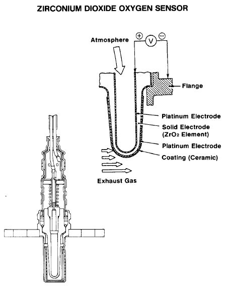


O2 sensor:
It basicly tells the ECU the amount of O2 in the exhaust compare to the amount ambient O2. When the engine is running rich there are very less oxygen particals present in the exhaust and more on the ambient side so there is more pressure as the outside Oxygen particals want to go where there is less oxygen particals so this pressure creats a higher voltage which at max it gets close to 1 Volts to the ECU. When we have a lean mixture there are more oxygen particals present in the exhaust manifold so therefor the pressure between each side of the o2 sensor is less and this causes less voltage output to ECU.

One of the draw backs of these sensor is that they need to be heated up first to around 300 celsious before it starts working . The ECU uses this sensor to go into closed loop as soon as it has been heated up and in working temerature to balance the air/fuel ratio mixture and it constantly going lean /rich .... as it is trying to find the optimum mixture for emmisions and performance .
It puts out nearly 1 volts when the mixture is too rich(very low oxygen levels in the exhaust) and close to 0 Volts when the mixture is lean (more oxygen present in exhaust)
Knock sensor off-car
Knock Sensor:
This sensor is pretty much in all the modern engines and it lets the ECU know if there are any knockes or detenations inside the cylinder . These knocks are produced by the engine when the timing is poor or if there is detenation due to too much advanced timing or a very lean fuel/air ratio mixture .The ECU also uses this to balance the timing if it is controlled by the ECU and to lean the air/fuel mixture or richen it if knocking.
This sensor uses piezo crystal and one of this crystal properties is when deform it creates a voltage . Knocking inside the cylinder causes the crystal to vibrate and therefore it creates a voltage to be sent back to the ECU so it can rectify it and delay the advance timing to stop it form knocking or richen the air/fuel mixture .
By connecting the sensor to oscilliscope and tapping the knock sensor we can see how this sensor works .
CTS sensor off-car


CTS , THw , ECT , ATS , IAT
These sensors job is to let the ECU know the temperature of various parts of the engine from the air going in ,to the coolent circulating around the engine also to turn the radiator fan on after a certin temperature so the engine wouldnt over heat. All these informations are needed to keep the engine in optimum temperature for performance and more importantly emissions.
These sensors are normaly NTC which means negative temperature co-efficient so as the temperature increases their resistance decreases so as the temprature rises so those the voltage signal back to the ECU .
For checking these type of sensor you can part of them in a bowl of water , heat the water up and check the resistance with a multimeter we can see how the resistance falls as the temperature increases .
MAP Sensor off-car
 As the pressure decreases inside the manifold so those the voltage output of this sensor

Manifold Absolue pressure: